|
COMPUTERS
|
|
SUPPORT
|
|
COMPARE
|
|
NEW
|
|
ABOUT US
|
|
WHERE TO BUY
|
|
SITE MAP
|
|
|
|
|
| Call Tech Support.
For fee-based technical support, please call
1-800-207-3434 or send
us an email.
Remember, it's important to have your system, model, or serial number
ready when contacting our support staff with technical questions.
Need help? |
|
| PowerSpec PC Systems: Support System Boards |
|
Applicable for PowerSpec models: 2120,
2210, 2211, 2212, 2220, 2221, 2410, 2430, 2431, 2620, 2621, 2622,
2630, 3410, 3411, 3612, 3610, 3611, 3412, 3710
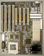
ECS P5HX-B System Board
P6HX-B Connectors
P6HX-B Jumpers
P6HX-B Memory
|
P5HX-B System Board Connectors
Note: some device connectors are manufacture options and may not
be present on all systems
|
Connector
|
Function
|
Description
|
|
J1
|
PS/2 Keyboard Connector
|
|
|
J2
|
AT Keyboard Connector
|
|
|
J3
|
PS/2 Mouse Connector
|
|
|
J4
|
Serial 1 (COM1/COM3)
|
|
|
J5
|
Serial 2 (COM2/COM4)
|
|
|
J6
|
Printer Port
|
|
|
J9
|
FDD Connector
|
Attach to floppy disk drive(s)
|
|
J10
|
Primary IDE Connector
|
Attach to Primary Master, Slave
|
|
J11
|
Secondary IDE Connector
|
Attach to Secondary Master, Slave
|
|
J12
|
Front Panel Switches and LED indicators
|
Pin connections:
2-3 Turbo LED positive, negative
4-5 SMI (Suspend Mode Input) switch
6-7 Turbo mode switch
9-10 Reset switch
11-15 Keyboard lock
17-20 Speaker
|
|
J13
|
HDD LED (Hard Disk Drive)
|
Pins 1,4 positive; pins 2,3 negative
|
|
J16
|
Cache Module Connector
|
|
|
J17
|
USB Header
|
Attach to 2 channels connector of USB bracket
|
|
J19
|
IR Header (IBM; manufacture option)
|
|
|
J20
|
IR Header (Intel)
|
|
|
J21
|
PS/2 Mouse Header
|
Attach to external PS/2 mouse
|
|
J22
|
CPU Fan Connector
|
(normal mode; manufacture option)
|
|
J23
|
CPU Fan Connector (Green Function)
|
P5HX-B provides the ability to turn the CPU cooling fan off while
the system is in low-power suspend mode. Connect the CPU cooling
fan to J23 and enable the "CPU Fan Power Green" function in the
BIOS "Power Management Setup" to activate this feature. Pins 1,3
Ground; pin 2 positive 12vDC.
|
|
J24
|
Green Function Indicator
|
Connect the LED to J24. The LED will blink when the system is
in low-power suspend mode. Pin 1 ground; pin 2 positive
|
P5HX-B Jumpers
Host Clock, CPU type and Speed settings
|
Core CPU Frequency (MHz)
|
Host Clock
|
JP4
|
Clock Multiplier
|
JP2*
|
JP3
|
|
75
|
50
|
short
1-2,
3-4
|
1.5
|
short
1-2
|
short
1-2
|
|
90
|
60
|
3-4
|
1.5
|
1-2
|
1-2
|
|
100
|
66
|
1-2
|
1.5
|
1-2
|
1-2
|
|
110
|
55
|
open
|
2
|
1-2
|
2-3
|
|
120
|
60
|
3-4
|
2
|
1-2
|
2-3
|
|
133
|
66
|
1-2
|
2
|
1-2
|
2-3
|
|
150
|
60
|
3-4
|
2.5
|
1-2
|
2-3
|
|
166
|
66
|
1-2
|
2.5
|
2-3
|
2-3
|
|
200
|
66
|
1-2
|
3
|
2-3
|
1-2
|
|
233**
|
66
|
1-2
|
3.5
|
open
|
1-2
|
|
* The Cyrix 6x86 CPU does not have multiplier
1.5 or 2.5 Leave JP2 open when installing Cyrix 6x86.
** The HX-B system board must have (flash) BIOS v 1.6d to support
233 correctly. JP11, 12, 13, 14 are all shorted 2-3.
The flash update file is available on the BSB and FTP site as P5HXB16D.ZIP
See readme.txt for instructions and cautions.
|
Cyrix 6x86 CPU core frequency settings
|
Cyrix 6x86
|
Core CPU Frequency (MHz)
|
Cyrix 6x86 CPUs and AMD K5 CPUs use the P-rating as the CPU frequency.
Refer to this table to get the Cyrix 6x86 CPU core frequency. For
AMD K5 CPUs, check your CPU vendor for detailed information.
|
|
P120+
|
100
|
|
P133+
|
110
|
|
P150+
|
120
|
|
P166+
|
133
|
CPU Voltage settings
|
Single Voltage CPUs
|
JP11, JP12, JP13, JP14
|
CPU Voltage
|
JP10
|
|
|
short 1-2, 1-2, 1-2, 1-2
|
3.3v (STD) [default]
|
short 1-2
|
|
3.52v (VRE)
|
short 3-4
|
|
Dual Voltage CPUs
|
JP11, JP12, JP13, JP14
|
CPU I/O Voltage
|
JP10
|
CPU Core Voltage
|
JP17 *
|
|
short 2-3, 2-3, 2-3, 2-3
|
3.3v (STD)
|
short 1-2
|
2.51v
|
short 1-2
|
|
2.73v
|
short 3-4
|
|
2.91v
|
short 5-6
|
|
3.52v (VRE)
|
short 3-4
|
2.51v
|
short 1-2
|
|
2.73v
|
short 3-4
|
|
2.91v
|
short 5-6
|
|
* Caution! Check your processor documentation for correct voltage
settings to avoid damaging the CPU.
Single voltage CPUs include Intel Pentium, Intel Overdrive series,
Cyrix 6x86, and AMD K5.
Dual voltage CPUs include Intel Pentium with MMX technology (P55C),
Cyrix 6x86L, M2 dual voltage, and AMD K5 Dual voltage CPU.
|
Cache Memory Size settings
|
Total Cache installed
|
JP15
|
JP16
|
|
0KB
|
open
|
open
|
|
256KB (256K on-board cache)
|
short
|
short 1-2
|
|
256KB (256K cache module only)
|
open
|
short 1-2
|
|
512KB (256K on-board 32Kx32 Burst SRAM and 256KB cache module installed)
|
short
|
short 3-4
|
|
512KB (256K on-board 64Kx32 Burst SRAM only)
|
short
|
short 3-4
|
Clear CMOS RAM
|
Operation
|
JP5
|
|
Normal (default)
|
short 2-3
|
|
Clear CMOS data
|
short 1-2
|
|
Hardware setting information and password data is stored in CMOS
RAM. To clear CMOS settings, short JP5 pins 1-2, power on the system,
power off the system, return JP5 jumper to 2-3 position.
|
P5HX-B Memory Installations
The following table shows several possible memory combinations. The P5HX-B
system board supports from 8-256MB. It supports up to 4 pieces of 72-pin
SIMMs; supports EDO or Fast Page Mode DRAM, supports parity or ECC function
with parity SIMMs installed.
|
Partial list of possible memory configurations
|
|
Bank 0
(must be installed in pairs)
|
Bank 1
(must be installed in pairs)
|
Total memory installed
|
|
SIMM1
|
SIMM2
|
SIMM3
|
SIMM4
|
Size
|
|
4MB
|
4MB
|
-
|
-
|
8MB
|
|
8MB
|
8MB
|
-
|
-
|
16MB
|
|
16MB
|
16MB
|
-
|
-
|
32MB
|
|
32MB
|
32MB
|
-
|
-
|
64MB
|
|
64MB*
|
64MB*
|
-
|
-
|
128MB
|
|
4MB
|
4MB
|
4MB
|
4MB
|
16MB
|
|
4MB
|
4MB
|
8MB
|
8MB
|
24MB
|
|
4MB
|
4MB
|
16MB
|
16MB
|
40MB
|
|
4MB
|
4MB
|
32MB
|
32MB
|
72MB
|
|
4MB
|
4MB
|
64MB
|
64MB
|
136MB
|
|
8MB
|
8MB
|
8MB
|
8MB
|
32MB
|
|
8MB
|
8MB
|
16MB
|
16MB
|
48MB
|
|
8MB
|
8MB
|
32MB
|
32MB
|
80MB
|
|
8MB
|
8MB
|
64MB*
|
64MB*
|
144MB
|
|
16MB
|
16MB
|
16MB
|
16MB
|
64MB
|
|
16MB
|
16MB
|
32MB
|
32MB
|
96MB
|
|
16MB
|
16MB
|
64MB*
|
64MB*
|
160MB
|
|
32MB
|
32MB
|
32MB
|
32MB
|
128MB
|
|
32MB
|
32MB
|
64MB*
|
64MB*
|
192MB
|
|
64MB*
|
64MB*
|
64MB*
|
64MB*
|
256MB
|
* 64MB SIMMs not tested at time of documentation.
|