|
COMPUTERS
|
|
SUPPORT
|
|
COMPARE
|
|
NEW
|
|
ABOUT US
|
|
WHERE TO BUY
|
|
SITE MAP
|
|
|
|
|
| Call Tech Support.
For fee-based technical support, please call
1-800-207-3434 or send
us an email.
Remember, it's important to have your system, model, or serial number
ready when contacting our support staff with technical questions.
Need help? |
|
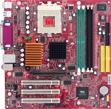
| PowerSpec PC Systems: Support System Boards |
Micro Star MS6738 Connectors
(click for larger view)
| Connector |
Function |
| AGP Slot |
The AGP video slot supports 4x AGP cards. |
| CONN1 |
ATX power supply connection |
| CPUFA1 |
CPU Fan connection |
| DIMM1, DIMM2 |
DDR DIMM slots (Caution! see memory detail.) |
| DIMM3, DIMM4 |
SDRAM DIMM slots (Caution! see memory detail.) |
| FDD1 |
Floppy Disk drive connection |
| IDE1, IDE2 |
Primary and secondary IDE connections |
| JBAT1 |
Clear CMOS jumper - Clear CMOS by shorting 2-3 pin while the
system is off, then return to 1-2 pin position. Warning! DO NOT
clear CMOS while the system is on; it will damage the mainboard.
|
| JAUD1 |
| For normal rear
audio connections, jumper 5-6 and 9-10. Caution: do not apply
jumpers in any other configuration! Damage to the system board
will occur. |
| Pin |
Signal |
Description |
| 1 |
AUD_MIC |
Front panel microphone input
signal |
| 2 |
AUD_GND |
Ground used by analog audio
circuits |
| 3 |
AUD_MIC |
BIAS Microphone power |
| 4 |
AUD_VCC |
Filtered +5V used by analog
audio circuits |
| 5 |
AUD_FPOUT_R |
Right channel audio signal
to front panel |
| 6 |
AUD_RET_R |
Right channel audio signal
return from front panel |
| 7 |
HP_ON |
Reserved for future use to
control headphone amplifier |
| 8 |
KEY |
No pin |
| 9 |
AUD_FPOUT |
Left channel audio signal
to front panel |
| 10 |
AUD_RET_L |
Left channel audio signal
return from front panel |
|
| JCD1 |
CD-in audio connector |
| JCI1 |
Chassis Intrusion Detector connection |
| JCOM2 |
Optional Serial Port2 connection. |
| JFP1 - Front panel connector |
| Pin |
Description |
| JFP1-1,3 |
Hard disk LED |
| JFP1-2,4 |
Power/Sleep MSG LED |
| JFP1-5,7 |
Reset Switch |
| JFP1-6,8 |
Power Switch |
| JFP1-9 |
Reserved. Do not use. |
| JFP2-1,5 |
Alternate Power LED |
| JFP2-2,8 |
Speaker |
|
| JFP2 - Front panel connector |
| JIR1 |
(optional) IrDA infrared module connector |
| JPW1 |
ATX 12V power connector |
| JSP1 |
SPDIF (Sony and Philips Sigital Interconnect Format) interface
for digital audio transmission. 1=vcc, 2=SPDIF, 3=not connected
|
| JUSB1 |
The mainboard provides one USB 2.0 pin header JUSB1 that is
compliant with Intel® I/O Connectivity Design Guide. USB 2.0 technology
increases data transfer rate up to a maximum throughput of 480Mbps.
|
| PCI (1-3) |
PCI expansion slots |
| SW1 |
Front Side Bus speed. With Power off and disconnected, set SW1
to the correct position BEFORE installing the CPU and powering on
the system. Incorrect setting of SW1 may cause a no-POST condition
or can damage older AMD Duron processors. |
| SYSFA1 |
System Chassis Fan connection |
| 
|
| PS/2 |
PS/2 Mouse/keyboard connector |
| USB Connectors |
Connecting to USB devices |
| COM A |
Serial port connector |
| VGA |
Integrated SiS 650 |
| LAN |
Integrated Realtek 8139 10/100 |
| Parallel |
Parallel port connector |
| L-Out, L-in, MIC |
Integrated Avance soft audio AC97 connections |
Micro Star MS6738 Typical Memory
Expansion
| DIMM1 DDR memory slot |
DIMM2 DDR memory slot |
DIMM3 SDRAM memory slot |
DIMM4 SDRAM memory slot |
Total System Memory |
32MB |
32MB |
empty! |
empty! |
64MB |
64MB |
empty |
empty! |
empty! |
64MB |
128MB |
128MB |
empty! |
empty! |
256MB |
512MB |
256MB |
empty! |
empty! |
768MB |
| 512MB |
512MB |
empty! |
empty! |
1GB |
1024MB |
1024MB |
empty! |
empty! |
2GB** |
| empty! |
empty! |
32MB |
32MB |
64MB |
| empty! |
empty! |
64MB |
64MB |
128MB |
| empty! |
empty! |
128MB |
empty |
128MB |
| empty! |
empty! |
128MB |
256MB |
384MB |
| empty! |
empty! |
256MB |
256MB |
512MB |
| empty! |
empty! |
512MB |
512MB |
1GB |
| empty! |
empty! |
1024MB |
1024MB |
2GB** |
* Total memory support is based on the actual combination of installed
DIMMs, not all possible configurations are shown. All installed DIMMs
should have the same speed. While physical characteristics such as manufacturer
brand, single/double sided may work in some combinations, problems have
been reported when mixing dissimilar RAM across banks.
** 1GB DIMMS should be supported for a maximum of 2GB total, but were
not available for testing at time of production.
Memory Population Rules:
- Warning! The MS6738 supports up to two 168-pin 3.3v SDRAM DIMMs
-or- up to two 184-pin DDR DIMMs (not both!) Installed memory is auto-detected
by the system. If SDRAM DIMMs are detected, the voltage required for
SDRAM operation will destory any low-voltage DDR DIMMs installed!
- Product documentation only shows support for PC2100 DDR memory.
- Expandable to a maximum of 2 GB of RAM, although your OS may limit
maximum supported. (Not more than 768MB is recommended for Win9x or
WinME. System may hang or actually slow down at or above this amount.)
Warning! Only install adapter cards or memory with the power cable
removed from the system. The system board still maintains power to devices
including the AGP, PCI and DIMM memory even in the "shut-down"
state. |